
the fuel minder™ store
Your # 1 Source for remote fuel-level indicators and accessories!
Tools Needed: flat head screwdriver,wire cutters/strippers, Allen wrench set,channel lock pliers, 2 3/8" hole saw or keyhole saw, a staple gun for small gauge wire, measuring tape, and vise grip pliers.
Before you begin: Here are some initial factors to consider
to make sure your installation goes smoothly. Determine a suitable mounting location for the power board. Choose one which is in close proximity to a 110 volt outlet, the oil tank, and to where you will be mounting the remote gauge. This alleviates the time spent running excess wire. Choose a location for the remote gauge which will be easy to fish a wire to, e.g. within an interior wall near the existing thermostat where a hole for the wire may already exist.
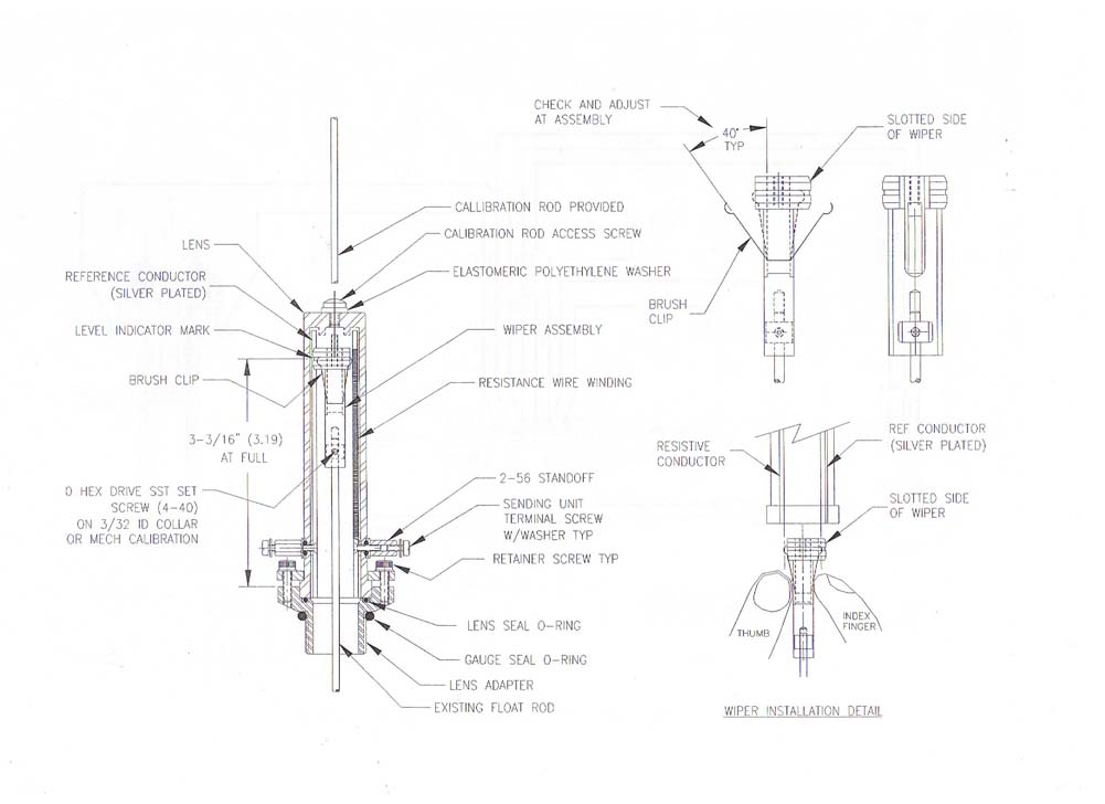
| A. Remove the existing tank gauge lens by simply unscrewing it from the existing gauge. Be sure to remove the existing gasket as well. | B. Remove the level indicator doughnut from the existing gauge by cutting the float rod just below the doughnut. (On OEM gauges the doughnut will unscrew from the float rod) |
 |
 |
| C. Screw the transition fitting into the existing gauge snugging it down with the channel lock pliers. | D. Pull up on the float rod to maximum full position. Secure vise grips on the bottom of the rod where it meets the lens adapter to hold into position |
  |
  |
| E. Slide the wiper onto the float rod until the red indicator mark on the wiper measures 3-3/16" from top edge of lens adapter. (see assembly drawing) Tighten the 4-40 set screw on the wiper collar to secure the wiper to the rod at the 3-3/16" measurement. Release and remove the vise grips once the wiper is securely attached to the float rod. | F. While compressing the wiper conductors between the thumb and fore finger, slide the lens assembly over the wiper making sure the slotted side of the wiper slides along the reference conductor (conductor without the wire winding). |
  |
  |
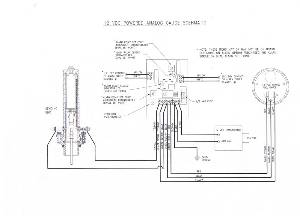
| H. Using a small flathead screwdriver, attach the 22 gauge wire to the terminal screws on the lens assembly. Run this wire to the power board and connect to the appropriate terminals. (See wiring diagram.) | |
 |
| A. Check for studs, electrical wiring or plumbing pipes in the location where you will be drilling. Mark and measure for hole, be sure to leave two inches on each side of the hole to accommodate the bezel. Make a 2 3/8" hole. Do not place in an exterior wall. Use an interior wall where there is no insulation or sill plates to contend with. To fit into the decor, the gauge should be mounted at a level which is conducive for ease of reading. |
 |
| B. Drill a 1/2" hole in the basement directly under the center of the remote gauge opening. An easy way to determine where this is, is to use a locator bit. This is a bit which is long and very small in diameter. Attach this to your drill and drill down in line with the center of the gauge opening as close to the wall as possible. Go downstairs and find the locator bit. Measure in the distance from the bit to the center of the inside of the wall, taking into consideration the width of the sheet rock or paneling which covers the wall then drill up into the wall. | C. Fish the wire up to the remote gauge opening. Take a piece of string with a weight on it (a 2oz fishing weight works well) and drop it from the remote gauge opening into the wall jigging it till it hits the wall plate below. Sometimes if you are lucky, it will fall through the hole below and will null the next step. Take a piece of fish tape with a hook on it and insert it into the 1/2" hole from below to catch the string and pull it through the hole. Attach your 22 gauge wire to the string and pull it up through the remote gauge opening. Run the wire from the gauge to the power board and connect it to the appropriate terminals. |
| D. Make sure all your wiring connections are correct before plugging in the transformer. Connect the transformer wire from the power board to the 12 volt transformer and plug it into the 110 volt outlet. |
| A. Unscrew the calibration rod access hole screw from the top of the lens assembly and screw the calibration rod into the top of the wiper | B. Pull up on the rod until the red mark on the wiper and the full mark on the lens meet. Attach the vise grips on the calibration rod so as to hold the wiper mark at the full mark. |
 |
C. View the remote gauge and make sure it reads full, repeat the above steps with the empty reading. |
| D. If the reading does not match with wiper in the empty position, adjust the zero adjust potentiometer up or down to make the remote gauge and lens markings meet each other. (See wiring diagram for the location of the zero adjust potentiometer location on PC board) Check full, 3/4, 1/2, and 1/4 readings on remote gauge. Repeat above steps if necessary. | E. If the readings above are normal, you now can permanently mount the remote gauge. Mount the remote gauge to the wall with supplied screws. |
TROUBLESHOOTING The Fuel Minder™
No reading on the gauge: Check and make sure you have 12 Volts DC coming into the power board from the transformer. Make sure transformer is secured into the outlet.
Inaccurate Reading: Make sure the 3-3/16" measurement
from the top edge of the transition fitting to the red marking on the wiper is at correct full height.
|
|---|
 |
|---|